Sensorbox
Software
Zentrale Steuerung
Erste Tests
Kabel C Buchsen CAN. 3a (CANL) - Ventilbox - 3c (CANL Rück), 3b (CANH) - Ventilbox - 3d (CANH Rück). Jedes Segment ca. 60m. 9,3Ω Schleife gesamt. 42,3Ω und 51,2mH (!) zwischen 3a/3b hausseits mit Ventil an 3c/3d hausseits. 106nF zwischen 3a/3b hausseits mit 100nF an 3c/3d hausseits.
Pololu DRV8801
Folks, I bought two https://www.pololu.com/product/2136 an am investigating the CS output when driving ENABLE by PWM. To understand better I've also looked at VPROPI before it enters the 10k on-module resistor.
According to discussion in https://e2e.ti.com/support/motor-drivers-group/motor-drivers/f/motor-drivers-forum, VPROPI has a bandwidth of 1MHz but is very weak (<100uA).
What I find is that at 30kHz PWM CS is rather stable due to being buffered behind the 10k by 33nF to ground. But I also find that VPROPI is being distorted by the load imposed by the 33nF through the 10k. At 66% duty cycle SENSE alternates between 180mV and 0mV, VPROPI alternates between 670mV and 395mV, and CS reads 575mV (close to the expected 600mV of five times 120mV average SENSE). At 33% duty cycle SENSE alternates between 90mV and 0mV, VPROPI alternates between 235mV and 95V, and CS it at 145mV (again close to the expected 150mV of five times 30mV average SENSE).
The Hunter PGV-100 valve (24Ω, 55mH) requires 300mA to switch on and then 80mA to stay on. With 15V supply and the DRV8801 (with a 500mΩ Rsense, PHASE HIGH and MODE1 HIGH) a 55% PWM duty cycle gives 290mA current through the valve in steady state (SENSE 145mV/0mV, CS 400mV), and a 15% PWM duty cycle gives 80mA (SENSE 40mV/0mV, CS 30mV).
Prototyp 1,2: aus Modulen
- Arduino Pro Mini, 5V 16MHz, https://www.arduino.cc/en/pmwiki.php?n=Main/ArduinoBoardProMini
- PD0 - RXD, PD1 - TXD, PD2-PD7 - D2-D7, PB0-PB5 - D8-D13, PC0-PC7 - A0-A7
- MCP2515/TJA1050 CAN module
- 2x DRV8833 H-bridge modules, C:/Users/Hobbyraum/Documents/Arduino/gardena_1251/drv8833.pptx
- HC-SR04 ultrasonic distance module
- I2C soil humidity sensor
- RG rain gauge with reed contact (rep. 0.011„ per tick, Ambient Weather WS-1080 replacement, https://www.amazon.de/gp/product/B07KYSXCBZ/ref=ppx_yo_dt_b_asin_title_o00_s00?ie=UTF8&psc=1)
- Measurement: 57.93cm² (52mm x 112mm mid of frame, -31mm² for four edges of ~6mm radius mid of frame),
- 106g water @ 20° → 50 ticks, 105.8cm³/57.93cm² = 18.2634mm, 0.365mm/tick (~0.014“)
- Gardena 1188-20 Bodenfeuchtesensor (1 Ohm wet, 10k dry)
- [3x TTP223 capacitive touch switches TS1/TS2/TS3, CMOS output (VCC-1V, GND)]
- 3x capacitive touch areas, CAP1203, SDA, SCL, VCC5V, GND
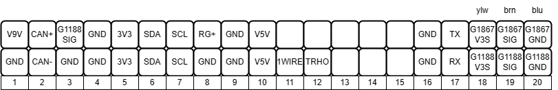
- Connections:
- VCC9V - 56k - A3 - 10k - GND
- VCC9V - |>MBRS130LT3G - VIN - 2200uF/16V - GND
- VIN,GND - TS295050 - VCS5V
- Pro Mini RAW - VIN, Pro Mini GND - GND
- D10 - CAN CS, D11 - CAN MOSI, D12 - CAN MISO, D13 - CAN SCLK, D2 - CAN INT, CAN VCC - VCS5V, CAN GND - GND
- D4 - HB BI1, D5 - HB BI2, D6 - HB AI1, D7 - HB AI2, A1 - HB1 NSLP, A0 - HB2 NSLP, A2 - HB NFLT?, HB VIN - VIN, HB GND - A7 - 2.2Ω - GND, HB1 BO1 - >|1N5819,120Ω - V1I, HB1 BO2 - V1O, [HB1 AO1 - >|1N5819,120Ω - V2I, HB1 AO2 - V2O, HB2 BO1 - >|1N5819,120Ω - V3I, HB2 BO2 - V3O]
- D8 - SR04 ECHO, D9 - SR09 TRIGGER, SR04 VCC - VCS5V, SR04 GND - GND
- A4 - I2C SDA - 2k2Ω - VCC5V, A5 - I2C SCL - 2k2Ω - VCS5V, I2C VCC - VCS5V, I2C GND - GND
- D3 - RG+ - 4k7Ω - VCS5V, RG- - GND
- A6 - G1188+ - 200k - VCS5V, G1188- - GND
- TS VCC - Pro Mini 5V, TS GND - GND, TS1 - 2k2 - A6, TS2 - 4k7 - A6, TS3 - 10k - A6
- TODO:
- Probe valve without disabling interrupts.
- Manufacture own board.
- Power loss valve shut capacitor and logic
- Measure air temperature and correct speed of sound accordingly.
- Build soil humidity sensor.
- Replace 120Ω by 150Ω (with DRV8833 voltage is around 8.5V, and we want to restrict the demagnetisation current to about the specified 50mA).
- Process CAN REBOOT request
- Case
- Process manual switches
- Support Gardena soil humidity sensor (see valvecontrol02, 1Ohm wet, 10kOhm dry, requires analog input pin for presence detection)
- Implement valve opening/closing plan
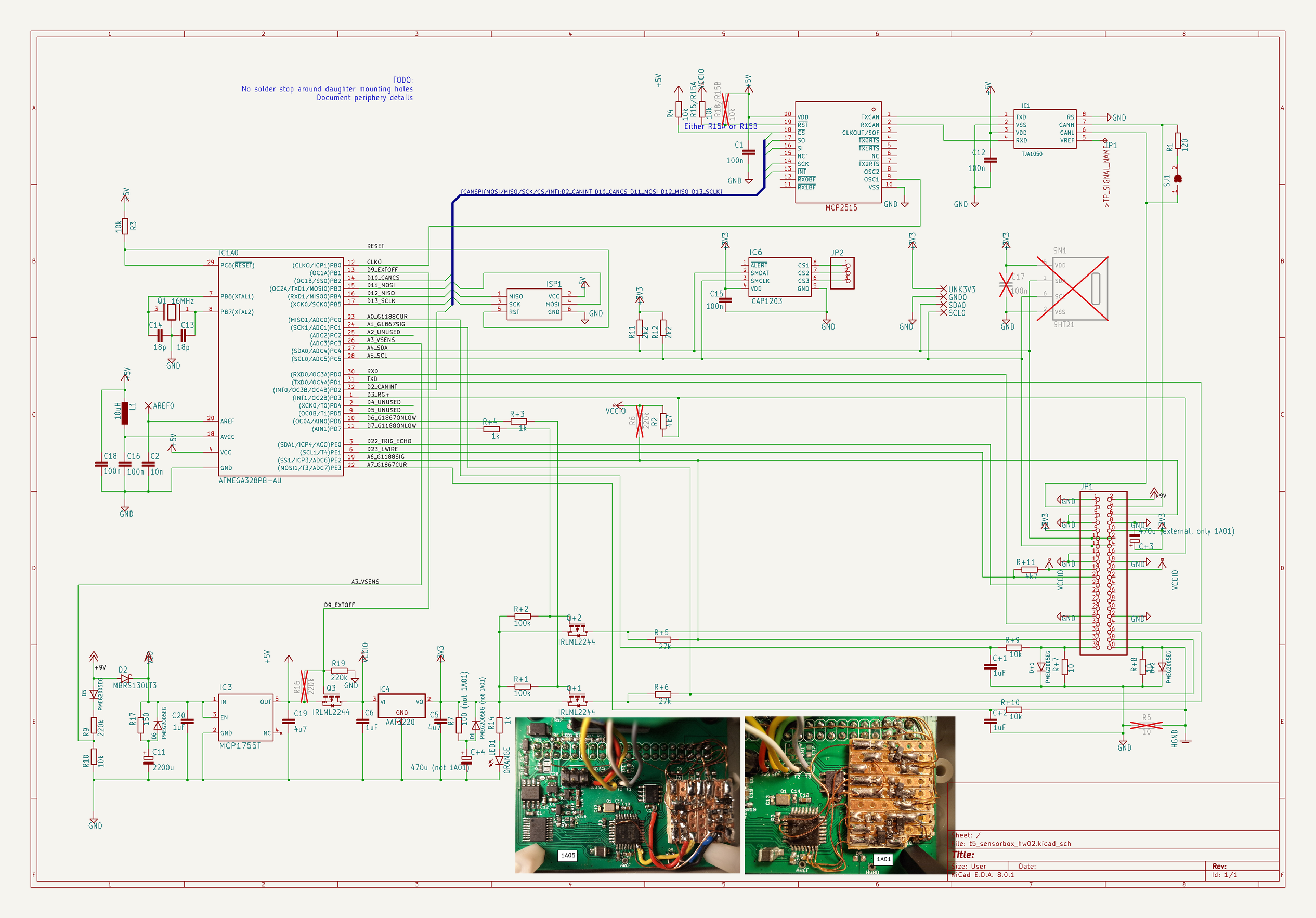
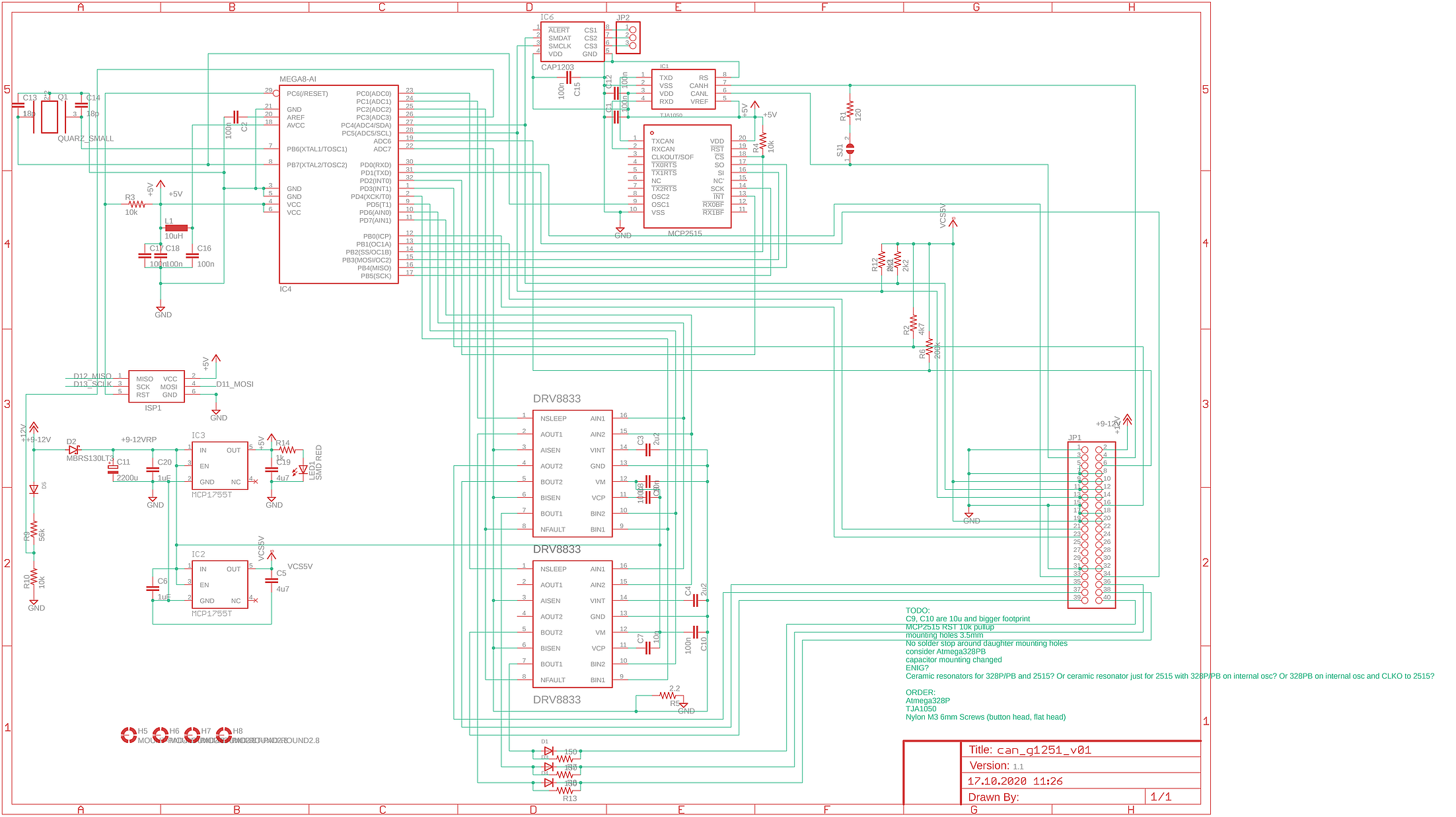
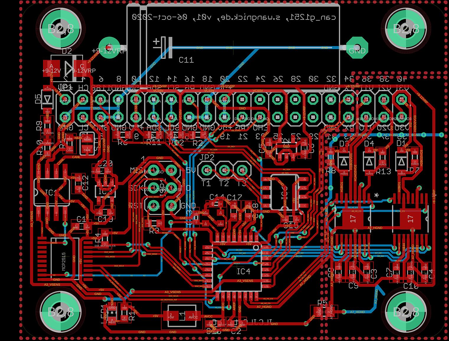
Prototyp 3: can_g1251_v01
Lange verbaut (als 0x1906): can_g1251_v01_mod
